VisiWeb Ethernet PoE Switch

The Ruf PoE switch is a central component of the VisiWeb PIS system. Thanks to its support of all common standards the switch can also be easily used in other systems in trains and buses. Its simple configuration via a web browser enables adaptation to all conceivable applications.

The PoE switch is an 8-port Ethernet switch with integrated PoE feed and specially hardened ports for Ethernet transmission via the vehicle’s e-coupling.

The switch can be integrated into the Ruf Ethernet ring via additional ports and its configuration and diagnostic features mean it fits seamlessly into the VisiWeb PIS system landscape. The switch supports the common IEEE 802.3 standards.

Features:

  • Manageable switch
  • PoE functionality (supply of terminals via the Ethernet cables)
  • Separate maintenance ports
  • Configuration via web interface
  • Loading of previously compiled configuration files from a notebook
  • All ports with auto-sense, auto-neg and auto MDI/X
  • The individual ports can also be configured to 10 Mbps or 100 Mbps
  • All Ethernet ports on chassis jacks are M12 D-coded, 4-pin
  • Up to four configurable PoE ports
  • Up to two specially hardened ports for communication via couplings, configurable to 10 Mbps / FDX
  • Two ports executed as electrically bridged ports for ring redundancy in case of error
  • The integrated power supply delivers the necessary internal and external power directly from the on-board electrical system without requiring an additional external 48V transformer
  • Optional redundant auxiliary power supply
  • Diagnostic feature via front LEDs
  • Readout of the settings, device status and device log files via a web interface
  • Software update via web interface

Ethernet Ports

A total of eight Ethernet ports are available, which can be configured according to your application via the web interface:
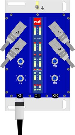
Ports X1 bis X4:
Ethernet interface with a data transfer rate of 10 Mbps or 100 Mbps. The interfaces can also be configured in such a way that external devices are fed via the Ethernet cables. This is implemented according to the Power over Ethernet (IEEE 802.3af) specification with performance class 1 (max. 3.84W per port).

Ports X5 und X6:
Ethernet interface with a data transfer rate of 10 Mbps or 100 Mbps. The interfaces are specially protected for Ethernet use via couplings. If the port is used for a connection via an electrical, operationally separable coupling, the port is to be configured to 10 Mbps / FDX, as higher data rates are not securely transferred here due to physical factors. The two interfaces can also be operated as a standard Ethernet port.

Ports X7 und X8:
Ethernet interfaces with a data transfer rate of 10 Mbps or 100 Mbps. The ports are provided to loop the switch in a ring topology. The two interfaces can also be operated as a standard Ethernet port.

The three ports at the lower part of the switch are available for the auxiliary power supply and maintenance purposes.

Anschluss X9:
The auxiliary power supply for the switch is provided via the chassis connector (M12, A-coded, 5-pin). It is possible to redundantly supply the switch (pin 1, pin 4). A binary group fault signal can also be queried via this port.

Anschluss X10:
The chassis jack (M12, A-coded, 4-pin) is intended for use as a service interface based on RS232.

Anschluss X11:
The chassis jack (M12, A-coded, 4-pin) is intended for the connection a configuration dongle.